OEM and ODM: we build the TPMS, you build the brand

Our own hardware and embedded software teams take a requirement from specification to production. That is why a customisation request does not stall between a trading company and an unknown factory.

Two ways to work with us

OEM

Build our product under your brand

Take an existing design — BPU100, TR100 or the IoT node — with your logo, packaging, colours and documentation. Fastest route to a sellable product line.

  • Your brand on the housing, packaging and manual
  • Alarm thresholds, units and report intervals set for your market
  • MOQ and lead time agreed per model and configuration
ODM

Build your product with our engineering

You bring the requirement and the market; we design the sensor, the radio, the firmware or the cloud side. This is where our full-stack team earns its place.

  • Custom firmware, protocol adaptation and API development
  • Enclosure, display UI and mounting designed for your vehicle
  • Certification scoped to your target market as part of the program

What we can change

Protocolcustom message sets, J1939, Modbus maps, BLE services and pairing flow
Firmwarereport interval, alarm thresholds, units, sleep and wake behaviour
Hardwaresensor form factor, valve type, battery choice, enclosure and connector
Display & UIscreen size, layout, icons, language and alarm presentation
Clouddashboard branding, alarm routing, REST API and data export
Packagingretail or bulk, artwork, manuals and label language

How a program runs

01

Scope

Vehicle type, wheel count, interfaces, environment, target price and volume.

02

Proposal

Configuration, wiring plan, sensor count, unit price and lead time.

03

Sample

Bench and on-machine evaluation with engineering support, then sign-off.

04

Production

Scheduled delivery, with QC records and traceability per batch.

05

After-sales

Local support in China plus remote engineering for firmware and integration issues.

Customer-specific work stays confidential: we do not display OEM customers' products or ship their designs to other clients. References can be provided under NDA.

GZVIA

How every unit is tested before it ships

A TPMS that fails in the field costs far more than the sensor. These are the checks we run in our own facility on every unit — with the equipment and the criteria we use.

QT-001

Sensor pressure and temperature calibration

100% inspection. Every sensor is checked for pressure and temperature accuracy, read and logged through calibration software we developed in house.

  • Equipment Reference pressure source · in-house calibration software
  • Criteria pressure ±7 kPa · temperature ±3 °C
Sensor pressure and temperature calibration
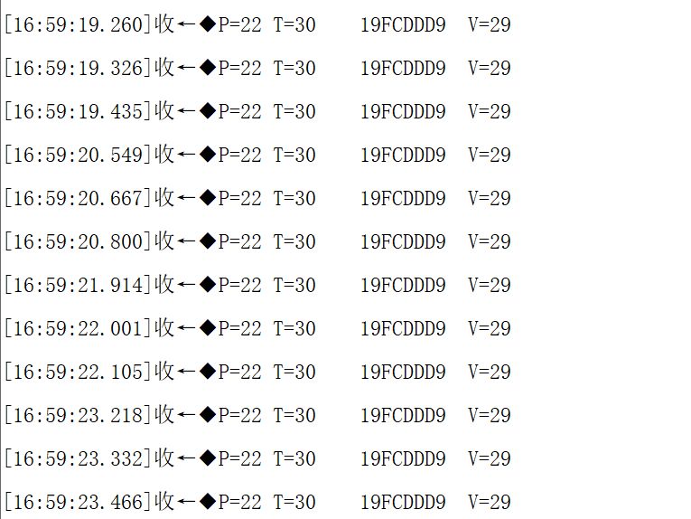
Live readings in the calibration software
QT-003

Water ingress / immersion test

Every sensor is immersed, then removed and inspected for water ingress and re-tested. The criterion is bubbles: bubbles mean a leak.

  • Equipment Immersion tank
  • Criteria IP68 · no bubbles, function confirmed on re-test
QT-005

RF communication range test

The receiver is tested with a dedicated reference transmitter to measure receive range, and the sensor with a dedicated reference receiver to measure transmit range — both verified against the ≥100 m specification on a purpose-built bench.

  • Equipment Dedicated reference sensor and receiver on a test bench
  • Criteria ≥100 m open air
RF communication range test
RF range test bench
QT-006

Full wheel-count system simulation

All sensors and repeaters laid out at the real wheel count to verify addressing, re-connection after dropout and alarm logic. This is what makes a 160-wheel delivery possible.

  • Equipment Wheel-position test rig / workshop fixture
  • Criteria every wheel addressable · dropouts re-connect · alarms fire correctly
QT-008

CAN / serial protocol and interface validation

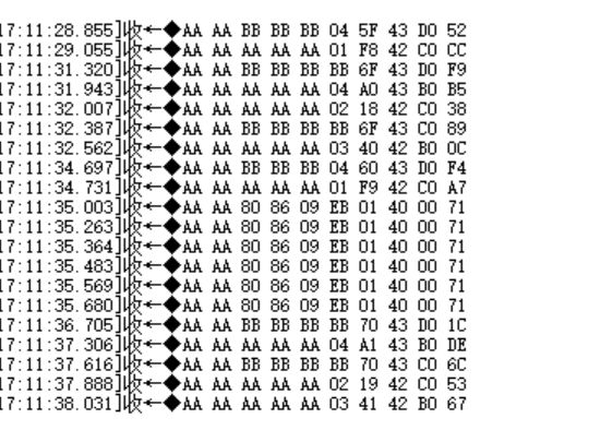
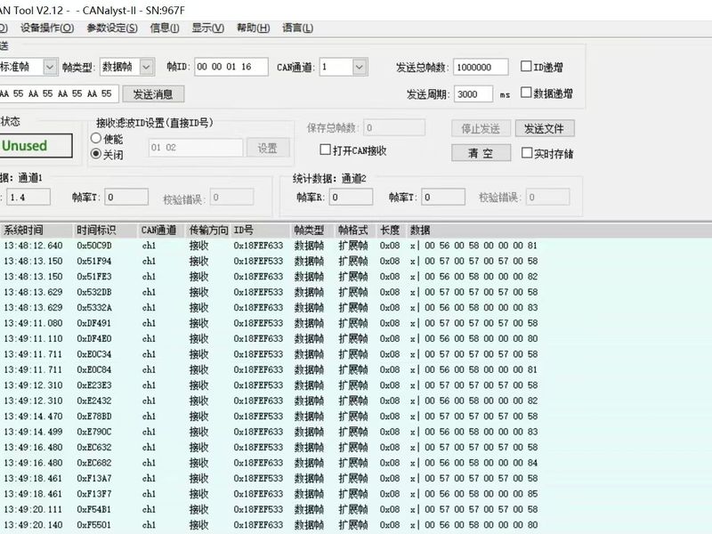
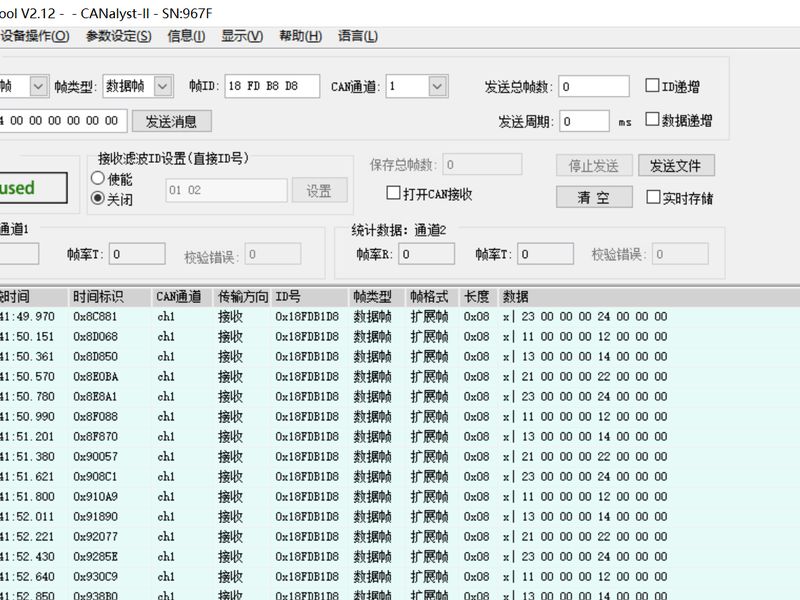
Live frames read with a CAN analyser and checked against the DBC / protocol document we deliver with the unit.

  • Equipment CAN analyser · host test software
  • Criteria frames match the delivered DBC / protocol document
CAN / serial protocol and interface validation
Live frames in the CAN analyser
CAN / serial protocol and interface validation
Frames checked against the protocol document
QT-009

Battery life and power consumption

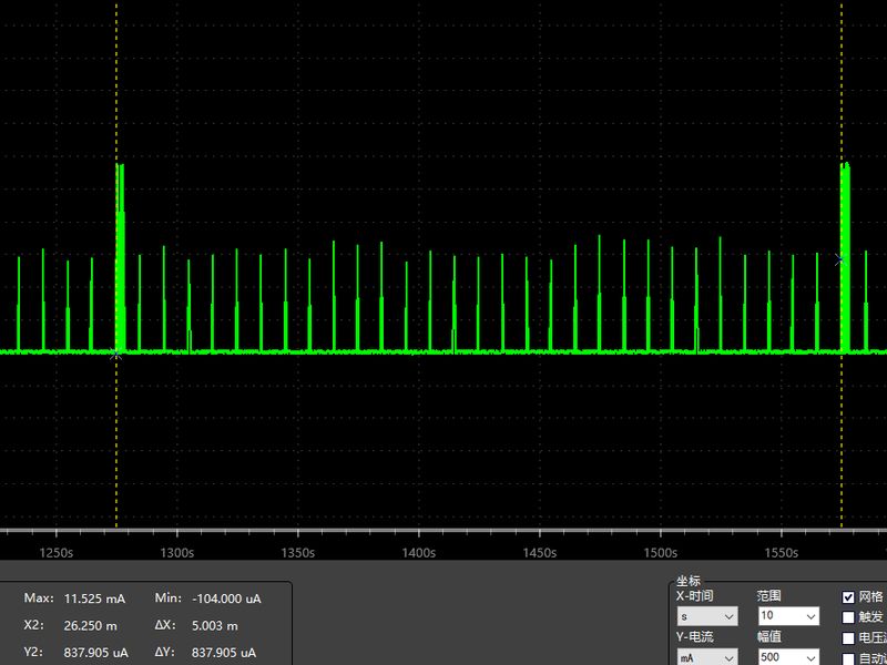
Current draw measured in each operating state with a multimeter / power analyser, then extrapolated to verify the rated battery life.

  • Equipment Multimeter · power analyser
  • Criteria internal ≥ 5–6 years · external ≥ 2 years
Battery life and power consumption
Power draw measured across operating states

Send the specification you need built

Even if it is half-formed — a requirement, a competitor product and a target price is enough to start a technical conversation.